
Gears are among the most crucial components in mechanical engineering, enabling the transfer and transformation of motion and force in everything from watches to industrial machines. In this article, we'll explore what a gear is, trace its historical roots, understand its purpose, look into its various types and how it's made, and finally examine the key parameters that define a gear's performance.
1. What is a Gear?
A gear is a mechanical component with teeth that interlock with those of another gear or toothed part to transmit torque and rotational motion. Gears are usually mounted on shafts and are essential for changing the speed, direction, and torque of a mechanical system. They come in various sizes and shapes, depending on their specific application and design requirements.
2. What is the History of Gears?
The use of gears dates back thousands of years and has evolved through many civilizations:
- Ancient Times: The earliest known gear system was the Antikythera mechanism (circa 150–100 BC) from ancient Greece, used for astronomical calculations. Ancient China also used gears in water-lifting and time-keeping devices.
- Middle Ages: Gears became more widespread in Europe, particularly in tower clocks, windmills, and mechanical devices.
- Industrial Revolution: The rapid advancement in machinery during the 18th and 19th centuries led to significant developments in gear technology and manufacturing methods.
- Modern Era: Today, gears are produced using highly accurate CNC machines, CAD software, and advanced materials, playing critical roles in everything from vehicles to space exploration.
3. What is the Function of Gears?
Gears serve multiple vital functions in mechanical systems:
- Transmit Motion: Transfer rotational motion from one shaft to another.
- Change Speed: Increase or decrease rotational speed.
- Alter Torque: Multiply or reduce torque to match load requirements.
- Change Direction: Redirect the axis of rotation.
- Convert Motion: Transform rotational motion into linear motion (as in rack and pinion systems).
These functions make gears indispensable in applications like automotive transmissions, power tools, clocks, elevators, and more.
4. The Classification of Gears
Gears are classified by tooth shape, shaft orientation, and gear design:
(1) Spur Gears
Straight teeth parallel to the shaft.
Spur gears are further divided into external spur gears and internal spur gears.
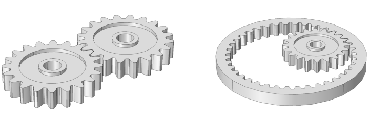
Simple and commonly used in low-speed applications.
(2) Helical Gears
Teeth cut at an angle to the face of the gear.
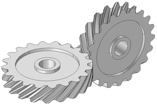
Quieter and smoother than spur gears, suitable for higher speeds.
(3) Bevel Gears
Conically shaped and used to transmit power between intersecting shafts.
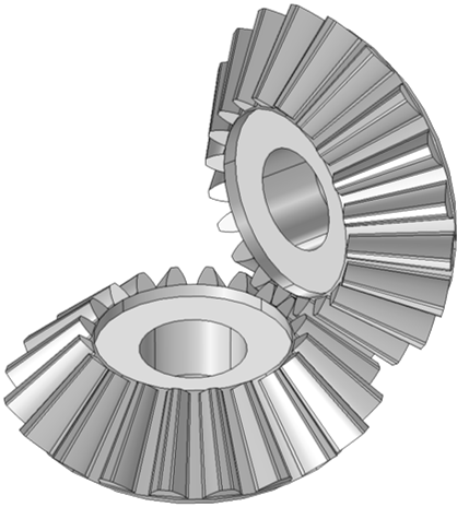
Often used in right-angle drives.
(4) Worm Gears
Consist of a worm and a worm wheel.
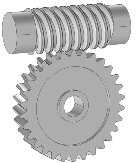
Allow large speed reductions and are often self-locking.
(5) Rack and Pinion
Converts rotational motion into linear motion.
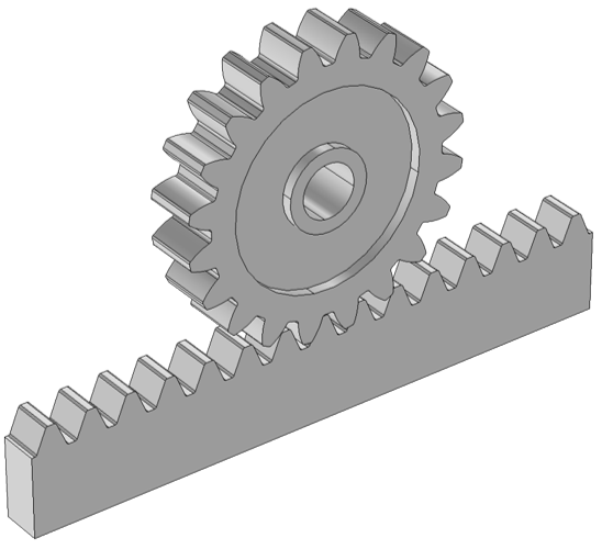
Used in steering systems and CNC machines.
5. The Manufacturing Method of Gears
Different methods are used to manufacture gears based on application, material, and required precision:
(1) Casting
Involves pouring molten metal into a mold.
Used for large gears where high precision isn't required.
(2) Machining
Includes hobbing, milling, grinding, and shaping.
Produces accurate and high-quality gears.
(3) Forging
Heated metal is shaped under pressure.
Produces strong, durable gears suitable for heavy-duty use.
(4) Powder Metallurgy
Metal powders are compacted and sintered.
Good for mass-producing small gears with moderate strength.
(5) 3D Printing (Additive Manufacturing)
Ideal for prototyping and complex shapes.
Currently limited to lower-load applications but advancing rapidly.
6. What Parameters Are There?
Gears are defined by several key parameters that determine their design and performance:
(1) Module (m)
The ratio of pitch diameter to the number of teeth; used primarily in metric systems.
(2) Diametral Pitch (DP)
Number of teeth per inch of pitch diameter (used in imperial systems).
(3) Pitch Circle Diameter (PCD)
The diameter of the pitch circle, where gears theoretically touch and transfer motion.
(4) Number of Teeth (z)
The total number of gear teeth, affecting gear ratio.
(5) Pressure Angle (α)
The angle between the line of action and the tangent to the pitch circle.
Common values are 20° or 14.5°.
(6) Gear Ratio
The ratio of teeth between meshing gears; determines speed and torque relationships.
(7) Face Width
The width of the gear teeth; affects load capacity.
(8) Backlash
The small gap between meshing teeth; necessary for smooth operation and to avoid binding.
(9) Addendum & Dedendum
Addendum is the height of the tooth above the pitch circle; dedendum is below it.
Understanding these parameters is essential for gear design, selection, and troubleshooting.
Conclusion
Gears are foundational to mechanical systems, enabling controlled motion and power transmission in everything from ancient clocks to high-tech robots. With a rich history, a variety of types and functions, sophisticated manufacturing techniques, and precise design parameters, gears remain a cornerstone of modern engineering. Mastery of gear fundamentals is essential for anyone involved in mechanical design, automation, or machinery.
Post time: May 08, 2011